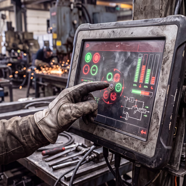
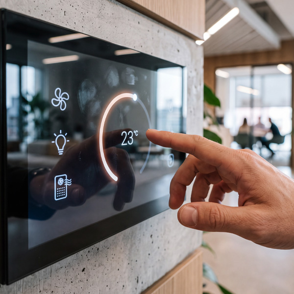
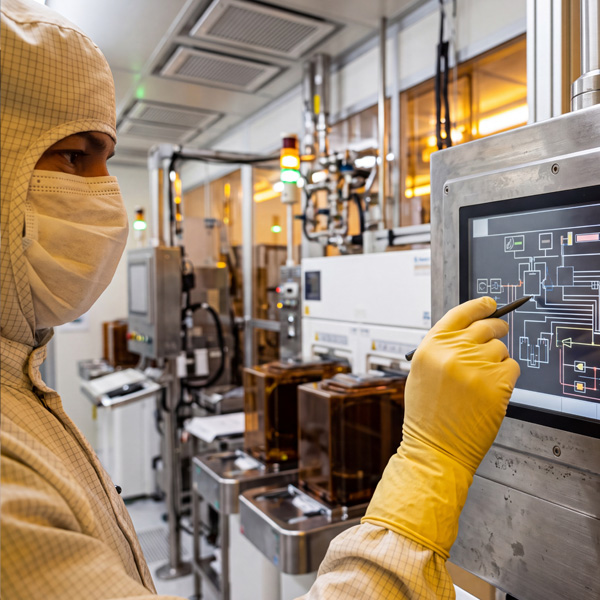
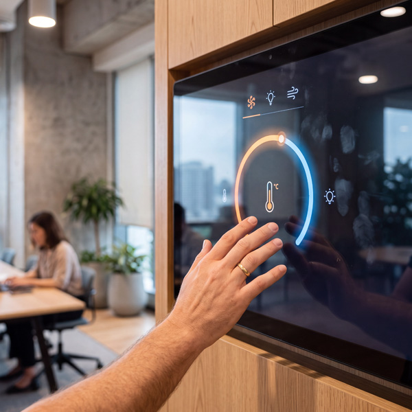
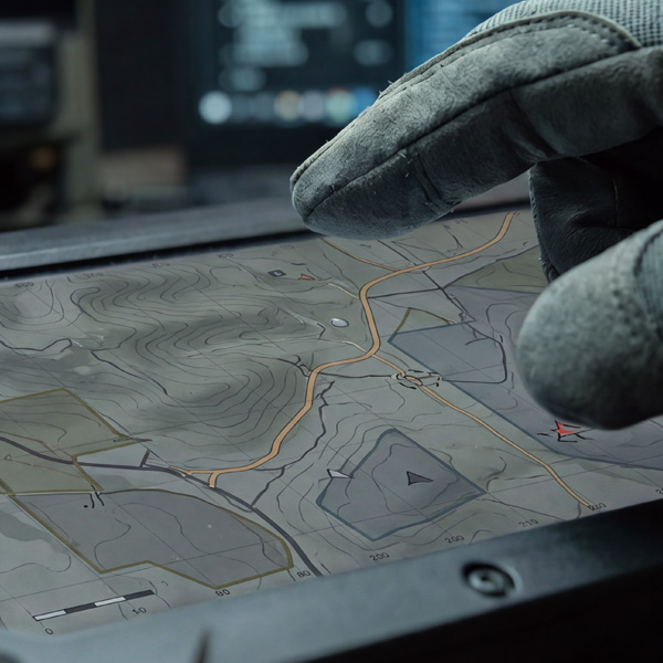
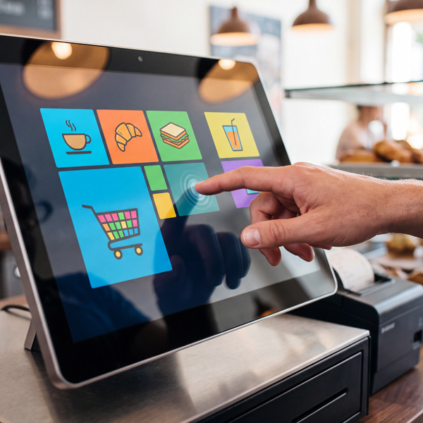
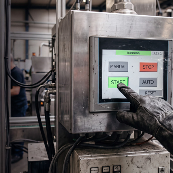
What is touch technology?
Touchscreen technologies for HMIs must always be considered as a complete assembly in professional environments. What matters is not only the sensor principle and controller, but the interplay of cover material, adhesive bonding, electrical connection, grounding, housing environment, firmware tuning and operational behaviour in the field.
For many modern device architectures, projected capacitive technology (PCAP) is the first choice, particularly when closed fronts, high-quality optics and intuitive operation are required. This is where GETT has a particular strength, such as with the InduSmart® BlackLine Panel-PCs as well as with customised touch and control solutions for industrial, medical and public applications.
Conceived by humans, visually realized with AI
Resistive systems remain relevant when pressure input, input with different media or robust single-touch operation are in focus. Within resistive technology, a distinction must be made between 4-wire and 5-wire systems, as both variants operate differently in terms of construction and differ in robustness, signal path and long-term behaviour. The technology decision is therefore never made in isolation, but on the basis of the actual application, the planned stack-up and the environmental conditions.
In professional environments, projected capacitive and resistive methods dominate. Other touchscreen technologies such as infrared, SAW or optical methods are technically interesting, but for compact device fronts, bespoke control units and integrated industrial HMIs they are only suitable in special cases. What matters is which touchscreen technology can be reliably transferred into robust, cleanable and long-term available operating concepts. The decisive factor is therefore less the pure functionality than the integration capability into an industry-proven product.
💡Tips from our R&D:
Select touchscreen technologies based on the overall system, not on the datasheet. In GETT projects, front assembly, installation situation, cleaning requirements and desired customisation are early decision drivers. The right question is not "Which touch technology is more modern?", but "Which technology works reliably in the final assembly?".
Find relevant content quickly
Comparing touchscreen technologies
Resistive
Resistive touch systems operate pressure-based with two conductive layers. They are technologically established, comparatively tolerant of many electrical interference and well-suited when working with gloves, styluses or other input media. The limitations lie primarily in optical quality, mechanical lifespan and modern gesture control.
Operating principle of resistive touch systems
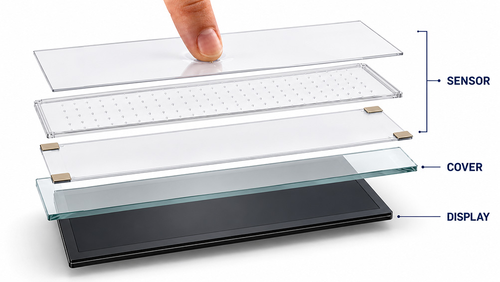
A resistive touchscreen typically consists of two transparent, electrically conductive layers separated from each other by fine spacers. When pressure is applied to the surface, the conductive layers touch locally. At this contact point, an electrical connection is created, through which position information dependent on voltage can be evaluated. The X and Y coordinates are measured sequentially by applying a defined voltage to one axis in turn and using the other axis as the measurement plane.
Input is thus independent of the electrical conductivity of the finger. A resistive system does not respond to a capacitive field, but to mechanical pressure contact. This is precisely why these touchscreen systems also work with gloves, fingernails, styluses or other pressure-exerting input media.
4-wire technology
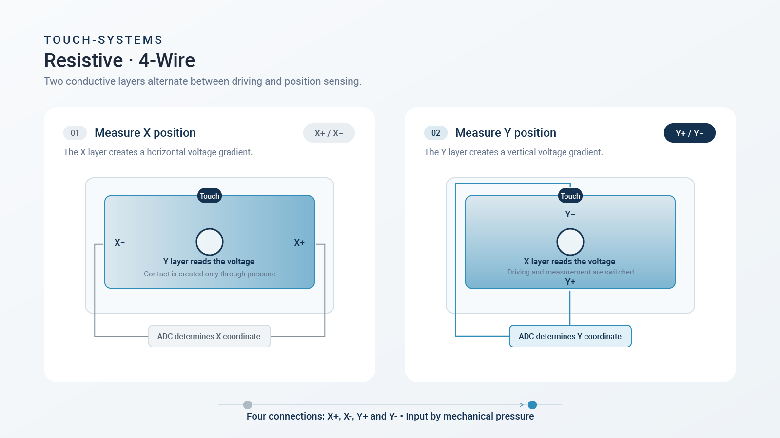
In a 4-wire resistive touchscreen, both the upper and lower conductive layers are actively involved in position measurement. Two connections are each assigned to one axis. To determine the X-position, a defined voltage is applied across the two edge contacts on one layer, creating a linear voltage gradient across the surface. When the user touches the surface, this voltage is transferred at the contact point to the opposite layer and recorded by the controller as a measured value. For the Y-position, the procedure is repeated with the layers reversed.
Position determination is thus achieved by alternately applying voltage to and measuring both conductive films. The system is constructively relatively simple and economical. At the same time, the upper flexible layer is electrically active and thus an integral part of the measurement system. Mechanical wear or ageing of this surface therefore directly affects measurement accuracy and long-term stability.
Conceived by humans, visually realized with AI
Technical classification 4-wire: economical, established and suitable for many standard applications, but more sensitive to surface wear than 5-wire systems.
Conceived by humans, visually realized with AI
5-wire technology
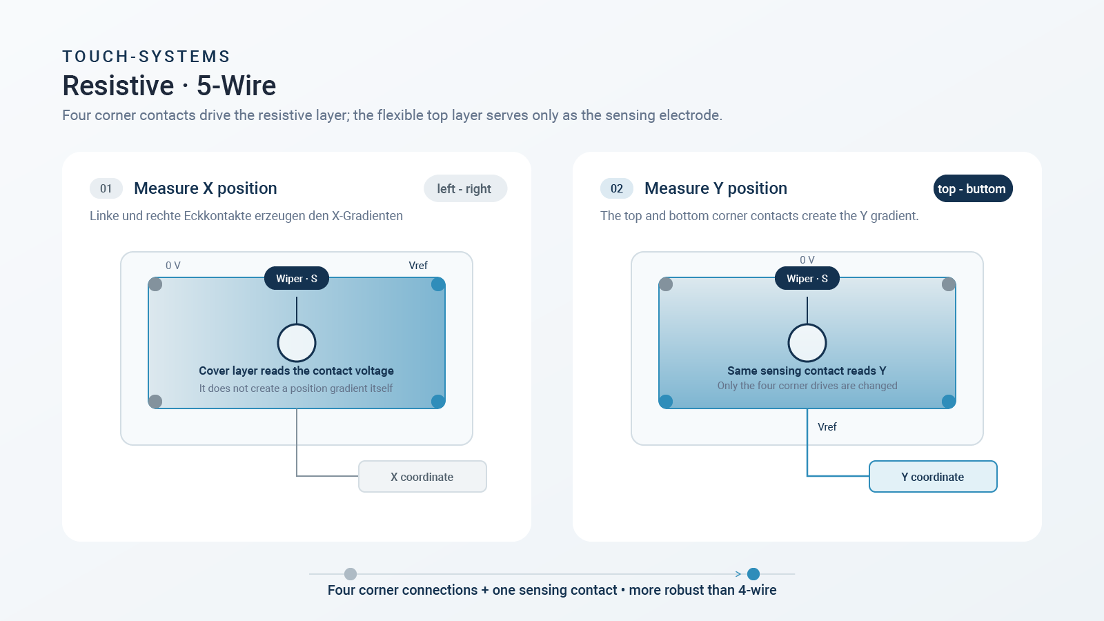
In a 5-wire resistive touchscreen, position measurement is primarily located on the lower, usually more stable glass layer. Four connections are located on this fixed substrate layer and generate defined voltage distributions for X and Y evaluation depending on the measurement cycle. The upper flexible layer serves primarily as a contact provider: when pressure is applied, it touches the lower layer and locally taps the voltage present there. This is passed to the controller via the fifth connection for evaluation.
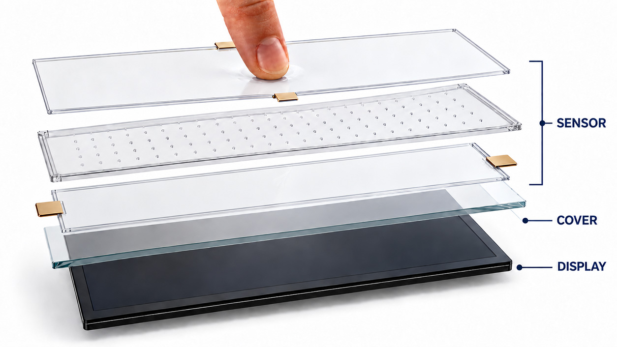
The constructive advantage: the electrically precise measurement plane is located on the more robust lower layer and not on the mechanically stressed cover film. Wear of the upper layer therefore has less impact on position determination than in 4-wire systems. 5-wire variants are therefore often considered more durable and stable in demanding applications with high cycle counts.
Technical classification 5-wire: more robust against surface ageing, often better suited to high stress, but usually more complex in design and not always the most cost-effective variant.
In GETT-oriented projects, resistive technology remains useful when robust functionality with simple operating logic, clear cost parameters or specific input media are decisive. For high-quality, seamless front concepts in hygiene or design applications, however, a capacitive architecture is more advantageous.
-
Distinguish between 4-wire and 5-wire not only by price, but by service life requirements
-
Assess mechanical lifespan of the active surface based on application requirements
-
Test with real input media and operating forces
-
Align display influence and optical quality requirements early
-
Dismiss resistive systems as outdated across the board
-
Underestimate long-term surface behaviour
-
Equate 4-wire and 5-wire functionally
-
Check design or hygiene requirements only after technology selection
💡Tips from our R&D:
Resistive is not resistive. When surface wear, lifespan and cycle count are critical, a conscious distinction must be made between 4-wire and 5-wire architecture.
Conceived by humans, visually realized with AI
Typical use cases 4-wire resistive
-
Simple control panels with clear single-touch interaction
-
Cost-sensitive devices with defined input behaviour
-
Applications operated with gloves, stylus or fingernail
-
Functional HMIs without special requirements for multitouch or premium optics
-
Legacy applications whose system architecture is designed for resistive technology
Technical rationale: 4-wire systems are constructively simple, economical and sufficient for many robust standard applications as long as surface wear and service life requirements remain within acceptable limits.
Typical use cases 5-wire resistive
-
Robust single-touch applications with high cycle counts
-
Control systems where the benefits of resistive input must be retained but higher service life is required
-
Industrial and special-purpose devices with gloved or stylus operation under simultaneous high mechanical stress
-
Applications where 4-wire is functionally sufficient but long-term stability needs to be improved
Conceived by humans, visually realized with AI
Technical rationale: 5-wire systems are particularly interesting when the benefits of resistive input are needed, but the actively measuring plane should remain as robust as possible against surface ageing.
PCAP
Conceived by humans, visually realized with AI
PCAP operating principle
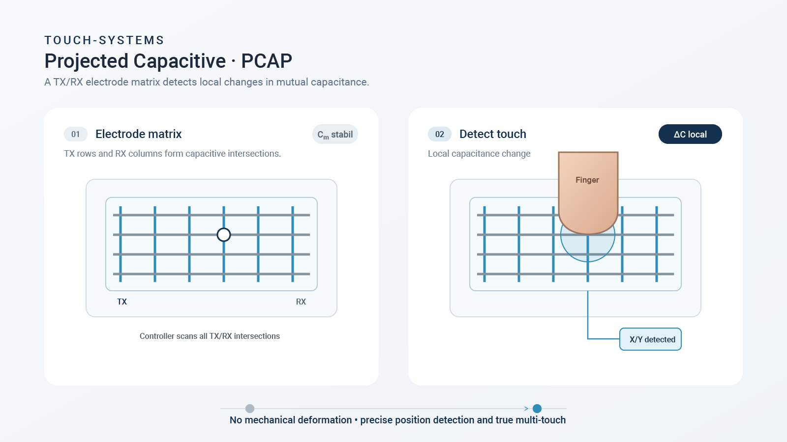
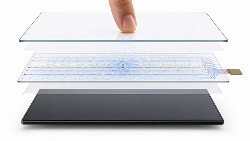
In projected capacitive touch systems, a fine structure of conductive electrodes is present on a transparent substrate material, usually in the form of transmitter and receiver traces in the X and Y directions. These electrodes are electrically isolated from each other and form an array of capacitive couplings at their intersection points. The controller sequentially excites the electrode pattern and measures the resulting capacitance values at the receiving structures.
When a finger or suitable conductive input medium approaches the surface, the electric field changes locally. Simplified: the finger acts as an additional capacitive path to ground and locally withdraws charge from the existing field. The controller recognises this change as a difference from the reference state, processes the raw data in matrix form and calculates the touch position from it. With multiple simultaneous changes, several touch points can be determined in parallel.
In real applications, PCAP is therefore not purely a geometric issue, but a signal-to-noise ratio problem. Cover glass, air gaps, adhesive bonding, moisture, conductive prints, metal frames, display noise and ground concept all influence field distribution and thus reliable detection. Actual performance emerges from the interplay of sensor design, controller hardware and firmware tuning.
In the GETT context, PCAP is particularly relevant for our InduSmart® BlackLine Panel-PCs, capacitive control interfaces and hygienically optimised operating solutions with smooth, easy-to-clean surfaces. Such systems are particularly powerful when sensor, front glass, housing, display and firmware are developed integratively.
-
Validate cover thickness and material early against controller and sensor range
-
Include metal environment, printing and edge design in electrical analysis
-
Test gloved operation, moisture and cleaning media with real samples
-
Automatically equate glass front with robust functionality
-
Transfer PCAP from consumer sector untested to industrial or medical applications
-
Release firmware tuning without final housing assembly
💡Tips from our R&D:
PCAP is a system decision, not a pure sensor decision. Especially with metal housings, bonding variants and closed fronts, the interplay of all layers determines later field stability.
Conceived by humans, visually realized with AI
Common applications for PCAP
-
Industrial panel PCs with modern user interface, e.g. GETT InduSmart BlackLine
-
Hygienic control interfaces in medical, laboratory and cleanroom environments
-
Machine HMIs with closed glass front and elevated design requirements
-
Public control solutions with high-quality front and intuitive touch interaction
-
Customised OEM products with customer-specific front design and modern UI logic
Technical rationale: PCAP is particularly useful when closed surfaces, good cleanability, multitouch and high-quality optical integration are required.
Other technologies
Further touchscreen technologies such as SAW, infrared or optical methods can offer advantages for special display sizes or transparency requirements. In compact industrial and device fronts, they are often less integration-friendly than capacitive or resistive solutions.
-
Evaluate special methods only with clearly identifiable technical advantage
-
Consider integration, sealing concept and environmental behaviour early on
-
Prioritise specialised technologies only for a single advantage
-
Underestimate effort for integration and qualification
💡Tips from our R&D:
Specialised methods are rarely the standard answer for industrial series production. They are worthwhile primarily when a specific application advantage justifies the additional integration effort.
💡Tipps from our R&D:
Selection between PCAP, 4-wire and 5-wire should be based primarily on input medium, service life, front design and integration environment. Not every robust application requires PCAP, but not every modern front can be realistically implemented with resistive technology. When a smooth front, cleanability and modern UI are required, PCAP is a strong choice. When input media and robustness are paramount, resistive can be the more pragmatic option. Typical use cases are not rigid assignments; what matters is the combination of input medium, service life, front architecture and environmental requirements in the project.
Where and when to use touchscreen technologies
Conceived by humans, visually realized with AI
Industrial applications
Typical boundary conditions include metal housings, vibration, contamination, gloved operation, switched loads, motor environment and complex ground references.
For industrial applications such as machine panels or control centres, this means: sensor, display, controller, housing and interface must be developed as a coordinated assembly. This is precisely where experience with industrial control solutions and panel PC platforms such as InduSmart BlackLine plays a central role.
-
Test metal-proximity assembly variants early
-
Verify display EMI and power supply environment in the overall system
-
Validate gloved operation with real users
-
Equate laboratory samples with series production behaviour
-
Define ground architecture only during electronics phase
-
Optimise touch and display separately
💡Tips from our R&D:
An industry-proven touch system is only robust when it has been tested in the final housing, with the final display and under real interference conditions.
Conceived by humans, visually realized with AI
Hygiene-sensitive environments
For GETT, these environments are particularly relevant, as hygienic control solutions, cleanable fronts and medically oriented concepts rank among core competencies.
Technically, hygiene operation is not purely a surface issue. What matters is also the durability of bonding and printing, behaviour with residual moisture, reaction to cleaning agents, glove compatibility and reliable function after repeated cleaning cycles.
-
Test materials and adhesives against real cleaning chemistry
-
Validate operation with typical glove types
-
Account for water films, droplets and cleaning residues in testing
-
Define hygiene solely by smooth surface
-
Assume chemical long-term resistance untested
-
Derive water rejection from standard configurations
💡Tips from our R&D:
Hygiene operation is a combination of front design, material durability, cleanability and stable input detection despite moisture and gloves.
Conceived by humans, visually realized with AI
Public environments
For customised GETT control solutions, it is particularly relevant here that front design, robustness and functional headroom are considered together. Public applications often benefit from closed fronts, clear UI concepts and robust housing integration.
-
Test ESD behaviour at real contact points
-
Align front material and housing with vandalism and cleaning requirements
-
Incorporate user diversity into the operating concept
-
Consider only sensor behaviour, not actual user contact
-
Underestimate weather or contamination effects
-
Decouple mechanical robustness from HMI architecture
💡Tips from our R&D:
Public applications do not just require a functioning touch system, but a robust front assembly with secure user contact path and stable field performance.
-
Release front design before sensor range and metal clearances have been evaluated
-
Decide on customisation without assessing impact on EMC, manufacturing and testability
-
Distinguish too late between standard module and custom solution
-
Conduct qualification only at component level instead of assembly and system level
-
Specify hygiene or industrial requirements only after prototype release
The background image was conceived by humans and visually implemented with AI.
💡Tips from our R&D:
The best technology is the one that can be integrated in the concrete use case with sufficient functional headroom. Many integration problems do not arise from the sensor itself, but from late decisions on front design, mechanics and housing integration.
Design and integration guide for touchscreen technologies
A robust design guide for touchscreen technologies covers four levels:
Conceived by humans, visually realized with AI
1. Layer structure and mechanics
Cover material and layer structure influence signal strength, haptics, cleanability, optics and long-term behaviour. Glass is often the preferred solution when cleanability, high-quality surface and mechanical stability are required. Plastic can be appropriate when weight, impact resistance or design freedom are priorities.
As cover thickness increases, the usable signal reserve decreases in PCAP systems. Additional decorations, hardcoats, printed layers or adhesive layers further increase complexity. Therefore, all layers must be considered electrically.
A robust stack-up includes cover, printing, adhesives, sensor, tail/FPC, shield planes, display connection, mechanical fixation and reference to housing ground. In customised GETT projects, this overall assembly is frequently the central lever for performance and series stability.
Particularly critical are edge zones, metallic holding structures, tail routing, air gap versus optical bonding and the position of screws, clips and shielding parts. Even small design changes can noticeably alter the electric field and thus touch performance.
-
Record all actual layer thicknesses in the stack-up
-
Include decoration, printing and coatings in electrical assessment
-
Validate material choices against cleaning and environmental demands
-
Create cross-section drawing of final front assembly at an early stage
-
Assess metal proximity in active and peripheral zones
-
Assess tail routing for both mechanical and electrical performance
-
Account for nominal glass thickness alone
-
Determine optical requirements separately from touch functionality
-
Consider bonding only from mechanical perspective
-
Let stack-up develop ad hoc instead of defining it upfront
-
Treat edge zones as mechanically non-critical
-
Suppose display integration has no effect on sensor performance
💡Tips from our R&D:
For touch functionality, what matters is not just the cover material, but the entire electrical and mechanical chain of effect above the sensor. The stack-up is not a documentation artefact, but the functional foundation of touch design. Changes must always be technically reassessed.
2. Optics and bonding
Conceived by humans, visually realized with AI
-
Specify bonding method jointly with display, cover and sensor selection
-
Assess bonding from electrical and optical perspectives simultaneously
-
Consider bonding only from mechanical perspective
-
Determine optical requirements separately from touch functionality
Conceived by humans, visually realized with AI
3. EMV/ESD-Design
In practice, EMC and ESD problems are often systemic. Critical are ground shifts, unclear reference potentials, interference coupling via displays or cables and uncontrolled discharge paths via metal parts and front areas. Clean field stability is achieved only through coordinated hardware, layout and firmware design.
-
Establish ground strategy linking sensor, controller, display and enclosure
-
Keep tail/FPC away from noise sources and high-speed traces
-
Factor metal frames, shielding and mounting structures into field planning
-
Assess display noise and power supply interference in system context
-
Validate ESD injection through front surface, frame and user touch points
-
Re-tune firmware after complete enclosure assembly
-
Test boundary conditions involving moisture, gloved operation and contaminated surfaces
-
Validate EMC/ESD both normatively and under realistic application scenarios
-
Include raw data logging to analyse interference
-
Address hardware issues before relying on software workarounds
-
Investigate ESD issues only when user interface failures occur
-
Use shielding without clear grounding strategy
-
Extrapolate field stability from lab testing
💡Tips from our R&D:
ESD and EMC are not final testing stages, but design tasks. In GETT-oriented industrial and hygiene projects, early robustness design determines later production readiness.
4. Gloved and wet-condition operation
Gloved operation is not automatic with PCAP. Whether it works depends on material, thickness, moisture, controller dynamics, electrode geometry and the entire interference environment. A reliable statement is only possible with real glove types in the final assembly.
Resistive systems work with gloves, fingernails, styluses or other pressure-exerting input media by design, as the method responds to mechanical pressure contact and not to a capacitive field.
In hygiene-sensitive applications, water films, droplets and cleaning residues must also be included in testing. Water rejection must not be derived from standard configurations but must be verified application-specifically.
Conceived by humans, visually realized with AI
-
Always specify touch systems together with front material, housing and firmware
-
Mechanically relieve tail/FPC and route it with low electrical noise
-
Evaluate conductive surfaces and metal proximity not only mechanically but also electrically
-
Incorporate hygiene and cleaning requirements early into material and technology decisions
-
Always verify customisation against functional headroom, manufacturability and serviceability
💡Tips from our R&D:
In custom projects, every customisation must be technically assessed: what appears optically sensible can be critical electrically or from a manufacturing perspective.
Reference stack-ups & example BOMs
The following references show typical stack-up and integration patterns from GETT practice and are intended as transferable architectural templates for your own projects.
The InduSmart® BlackLine exemplifies modern industrial control concepts with closed front, robust housing integration and capacitive touchscreen operation. For developers, it is particularly relevant how front design, cleanability, UI modernity and industrial suitability are brought together into a reliable HMI platform.
The system logic is transferable: touch sensor, display, front glass, housing and software are not considered separately but as a technically coordinated unit. This approach is precisely what matters for custom OEM projects as well.
💡Tips from our R&D:
When a project requires a closed, modern and cleanable front, our BlackLine is a useful reference framework for system architecture.
Applications with functional focus or different priorities regarding cost, operating logic and integration depth demonstrate that not every project requires the same HMI depth. What matters is clear prioritisation of must-have and nice-to-have requirements.
💡Tips from our R&D:
Not every application requires maximum UI complexity. Often, robust, clearly specified functionality is more important than an over-engineered HMI architecture.
Conceived by humans, visually realized with AI
Standard modules and customisation
GETT combines standard solutions with customer-specific adaptation. This customisation can affect dimensions, tail position, front design, printing, lighting, interfaces, material selection or operating behaviour. For OEMs, this represents a significant advantage: the solution can be adapted to application, installation space and user profile without starting from scratch.
From a development perspective, what matters is that every customisation creates technical interactions. A changed decoration can influence sensor characteristics, a different housing integration can alter EMC behaviour and a different front material can shift the operating margin.
-
Always plan customisation together with risk and feasibility assessment
-
Include electrical assessment in front design changes
-
Understand standard modules as a starting point, not as an automatic solution
-
Treat optical modifications as functionally neutral
-
Accept late special requests without re-qualification
-
Mix standard and custom during the project process
The background image was conceived by humans and visually implemented with AI.
💡Tips from our R&D:
The strength of customisation lies not only in adaptability, but in controlled technical derivation. Every change must be evaluated against functionality, manufacturing and qualification.
Specifications, standards and testing for touchscreen technologies for HMIs
For robust specification of touchscreen technologies for HMIs, electronics, firmware, interfaces and a complete project data package are decisive.
Interfaces and firmware
Electrical connection typically occurs via I²C, SPI, USB or controller-specific interfaces. What matters is not only protocol and pinout, but cable length, reference potential, connector concept, diagnostic access and noise immunity in the real device.
At firmware level, thresholds, baseline tracking, scan parameters, filters, glove profiles, water rejection and debounce affect field behaviour. GETT-specific customisation often means that standard parameters are insufficient and application-specific tuning is required.
-
Provide debug and raw data access already in early prototypes
-
Perform controller tuning in the final housing
-
Protect interfaces against ground shifts and interference
-
Carry over reference settings unchanged into production
-
Release host connection without diagnostic path
-
Consider firmware independent of mechanical assembly
The background image was conceived by humans and visually implemented with AI.
💡Tips from our R&D:
Controller and firmware are part of system integration. Good sensor technology does not compensate for inadequate tuning, and good tuning does not compensate for unsuitable stack-up.
test and specification data package
For technical clarification of a touch project, the following data should be available as early as possible:
-
Input media: finger, glove, fingernail, stylus, tool
-
Front material with thickness, coating, decoration and optical requirements
-
Display type, display noise, air gap or optical bonding
-
Installation space, metal environment, grounding points, housing concept
-
Temperature range, humidity, cleaning media, particulate contamination
-
Electrical interface, host platform, cable lengths and connectors
-
Standard requirements for ESD, EMC and environmental testing
-
Target volume, variant strategy and serviceability requirements
The background image was conceived by humans and visually implemented with AI.
💡Tips from our R&D:
The earlier real stack-up data, ground references and input conditions are available, the lower the risk of later integration loops.
We look forward to discussing with you!
Head of Innovation and Technology / Senior FAE
LinkedIn

- Application and operating concept
- Mechanical front assembly with material and thickness specifications
- Display and bonding concept
- Conductive environments, metal surfaces and ground architecture
- Electrical host connection and firmware requirements
- Environmental and qualification requirements including ESD and EMC
- Prototyping, testing and release strategy
This allows early assessment of whether a standard approach is sufficient or whether sensor layout, controller tuning and mechanical integration must be application-specific. Because a good project briefing not only reduces development time, but above all iterations on mechanics, electronics and front design.
The background image was conceived by humans and visually implemented with AI.
💡Tips from our R&D:
For a robust technical assessment, information on stack-up, input media, housing material, display integration, interface, environmental conditions and EMC/ESD requirements should be available at project start. The earlier these parameters are known, the more targeted touchscreen technology, controller and front assembly can be defined.
FAQs for technical decision-makers
Why does a touch sensor work well in the prototype but become unstable in the production housing?
Because housing metal, grounding, display integration, tail routing, power supply environment and real front materials can significantly alter electrical behaviour. Valid statements are only possible after integration into the application-relevant assembly.
Can a controller compensate for all integration problems via firmware?
No. Firmware can filter, adjust thresholds and reduce false triggers, but cannot fully compensate for unsuitable stack-up, poor ground architecture or problematic metal environment.
Is gloved operation always possible with PCAP?
No. Whether gloved operation works depends on material, thickness, moisture, controller dynamics, electrode geometry and the entire interference environment. A reliable statement is only possible with real glove types in the final assembly.
When should 5-wire be used instead of 4-wire?
Whenever the benefits of resistive input need to be retained, but higher mechanical stress, longer service life or more stable long-term performance are required.
What information is most often missing in early projects?
Often, detailed information about the real front assembly, conductive environments, grounding and actual input conditions is missing. Yet these are precisely the factors that determine later performance.
The background image was conceived by humans and visually implemented with AI.
💡Tips from our R&D:
The most common field problems do not arise from unknown effects, but from missing input data in the concept phase.
Autor
Where experience meets expertise