Zentrale
Sales

Optical sensors for touchless input systems

Conceived by humans, visually realized with AI

What are optical sensors and what are they used for?

Optical sensors (also called optical pushbuttons or optical switches in the context of input systems) enable contactless input. Unlike capacitive systems, which typically require a light touch, optical systems detect approach, movement, or simple gestures purely optically, without physical contact with the surface.

Quickly access the relevant content.


Technology that intelligently bridges distances

True touchless interaction offers valuable advantages for applications with the highest demands on hygiene, design freedom, and robustness.

Based on Time-of-Flight (TOF) or a reflective principle, the technology detects movements, gestures, or proximity purely optically – entirely without physical contact with the surface. This opens up new perspectives for hygienic, wear-free, and future-proof operating units.

A typical, concrete target application is the implementation of an optical button or optical switch (short-range); with TOF, simple gestures are also possible.

Conceived by humans, visually realized with AI

Technical Profile
Parameter
Reference Values
Sensing Range (Input)
depending on use case/sensor up to 1 m
Typical Operating Distance
up to ~30 cm, dependent on optics/mechanics/environment (more possible)
Resolution (ToF)
up to 1 mm possible (sensor-/configuration-dependent)
Sensing Angle / Geometry
ToF: typically narrow/directional; reflection: medium, cone-shaped
Timing / Feel
primarily firmware-determined (e.g. holdoff, filter, trigger logic)
IR Signal
typically modulated
Cover Material
transparent, ideally ≥ 80% transmission, 2–4 mm thickness; coatings without scattering/filtering
Protection / Hygiene
sealed surface enables high IP protection ratings and simple cleaning; glass often chemical-resistant (application-dependent)

How do optical sensors work?

Optical input systems often emit IR light and evaluate the returned signal. There are two principles involved:

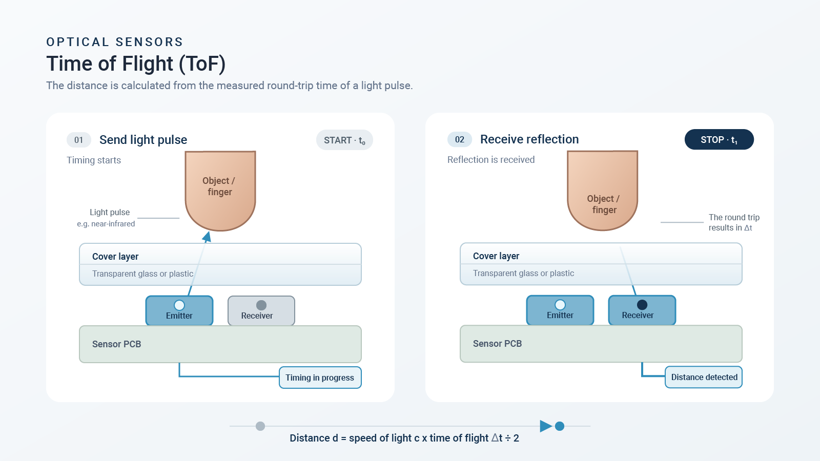
1. Time-of-Flight (TOF):
Distance measured via
runtime measurement

2. Reflexionsprinzip:
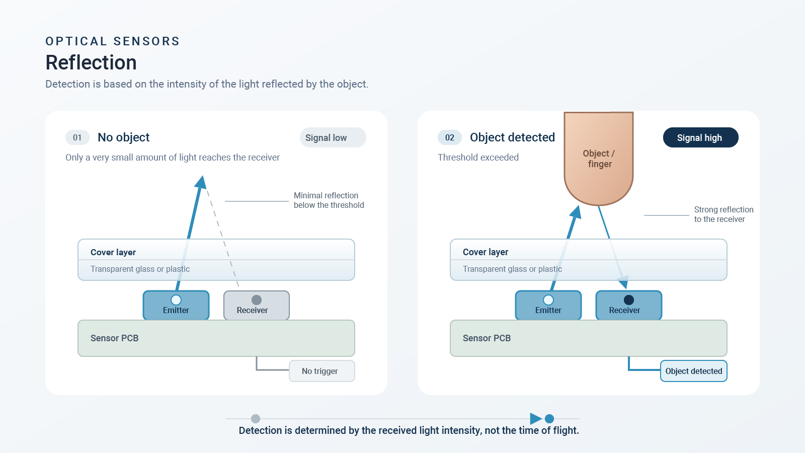
Triggering via intensity
(threshold) of reflection

Conceived by humans, visually realized with AI

💡Tips from our R&D department:

The measurement result is highly dependent on the system (sensor + optics/FOV + cover + mechanics + firmware). Therefore:

  • Always conduct early tests with real cover material and final mechanics (not just the sensor on the lab bench).

  • Treat parameterization (filter/holdoff/trigger) as part of the system design from the very beginning.

Comparison of TOF mini-box vs. reflection
Criterion
Time-of-Flight (ToF)
Reflection Principle (Threshold)
Measurement Principle
Transit time measurement of light pulse
Measurement of reflected light quantity
Result
Absolute distance (linear)
Trigger at threshold (non-linear)
Surface Dependency
low (transit time, not light quantity)
higher (reflection characteristics)
Robustness with Varying Surfaces
tends to be better
tends to be more critical
Sensing Angle
typically narrow/directional (optics-dependent)
typically medium (optics-dependent)
Integration Effort
higher (calibration/software)
lower (threshold logic)
Typical Interference Factors
Ambient light, line of sight, contamination

💡Tips from our R&D department:

In both cases, an "event" can be triggered simply by approach; "contact" is not required.

Time-of-Flight (TOF)

In time-of-flight (TOF) scanning, an infrared signal is emitted (often modulated). The electronics measure the time it takes for the reflected signal to return. The distance is calculated from this travel time.

  • Key message: Flight time (t1+t2) is a measure of the distance → TOF = Time of Flight
  • Measuring range: Depending on the sensor/setup, up to 1 m
  • Resolution: down to 1 mm possible (sensor/configuration dependent)
  • Surface robustness: less sensitive to changing surfaces, as primarily transit times and not light quantities are evaluated.

Conceived by humans, visually realized with AI

Advantages:
  • Absolute linear distance measurement instead of approximation
  • Recognition of simple gestures (e.g., swiping, approaching)
  • Largely independent of the object's surface material
  • No mechanical wear, suitable for high stress applications.
  • Generally EMC-robust due to optical measurement; however, the overall system depends on the layout, power supply, cables, and the ESD/surge concept.
Challenges:
  • Ambient light (e.g., direct sunlight) must be taken into account.
  • Line of sight required; contamination in the beam path interferes
  • Integration effort (calibration/software handling)
  • Assembly/alignment relevant

Conceived by humans, visually realized with AI

Reflexionsprinzip

In the reflection principle, IR light is emitted and the reflected signal is evaluated. If the detected intensity exceeds a defined threshold, an "event" is triggered. Detection is not based on an absolute distance measurement. Depending on the sensor and setup, ranges of up to 1 m are possible.

Advantages:
  • Simple measuring principle

  • Easy assembly, low tolerance requirements

  • Flexible design (e.g., multiple LEDs possible)

  • No mechanical wear

  • Generally EMC-robust due to optical measurement; however, the overall system depends on the layout, power supply, cables, and the ESD/surge concept.

Challenges:
  • Ambient light (sun) can have an effect

  • Line of sight/pollution critical

  • Stronger dependence on the surface/reflection

When are optical sensors generally useful?

Optical sensors are useful when touchless operation or closed, cleanable fronts are required.

A strengths and weaknesses comparison
When is the technology suitable?

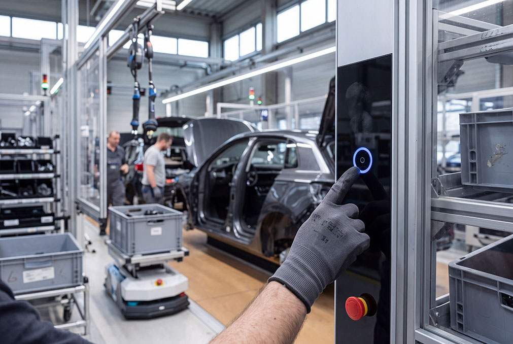
This technology is particularly suitable for applications with high demands on hygiene and cleanability. Optical pushbuttons and switches can operate without mechanical openings thanks to closed surfaces, for example, behind glass. At the same time, the contactless principle enables wear-free and long-lasting operation. Operation with gloves is also easily possible, which is a clear advantage over capacitive technologies. A prerequisite for reliable function is that the line of sight and beam path can be implemented cleanly in the design.

Conceived by humans, visually realized with AI

Where does the technology reach its limits?

The technology reaches its limits particularly with heavy or uncontrollable contamination in the beam path, as this can affect signal quality. direct sunlight also poses a challenge without suitable countermeasures or intelligent algorithms, which is why outdoor applications are significantly more demanding. Furthermore, the technology requires that a clear and reliable line of sight can be structurally ensured.

Conceived by humans, visually realized with AI


Advantages:
  • Genuine lack of physical contact (approach, gesture)
  • Very good hygienic properties (closed surface)
  • High IP protection ratings possible (system dependent)
  • Wear-free
  • Generally EMC-resistant; the overall system remains dependent on layout, power supply, cables and the ESD/surge concept.
Herausforderungen:
  • Direct sunlight and heavy pollution should be avoided or detected/treated via firmware.
  • TOF: higher firmware/calibration effort

Technical guidelines and system boundaries for the optical sensors

  • Distance & work area:

    Depending on the use case, up to 1 m; typical push-button operation often ≤ 30 cm

  • Field of view (FOV):

    TOF typically narrower, more directional; reflection usually medium (depending on optics).

  • Resolution:

    TOF down to 1 mm possible

  • Timing/“user feel”:

    Firmware parameters such as Holdoff and Filter determine latency and false trigger rate

  • Ambient light:

    Modulated IR helps; direct sunlight remains critical (possible outdoors, but more challenging)

  • Pollution:

    Avoid heavy contamination in the optical path; ideally, use firmware detection/degradation handling.

  • Covermaterial:

    ≥ 80% transmission, 2–4 mm; coatings must not scatter or filter.

The background image was conceived by humans and visually implemented using AI.

💡Tips from our R&D department:

Direct sunlight can saturate the receiver; countermeasures include optical shading and suitable filters or optics (sensor-dependent).

Important note regarding standards for laser-based emission

Not every IR light source is a laser; IEC 60825-1 is particularly relevant for laser-based emitters. For systems with laser-based light, it must be ensured that the input system meets the requirements of IEC 60825-1 (eye-safe).

The specific classification and verification must be clarified on a project-specific basis and incorporated into the system design (appearance, performance, operating modes) at an early stage.

Integration and system architecture

A robust input system results from the interplay of sensor, optics, mechanics, cover material, and firmware. The design is crucial for reliable operation: Decoupling the transmitter and receiver (avoiding optical crosstalk) and managing partial reflections at material interfaces (e.g., air-cover, cover-coating) are essential. Mounting close to the cover material is often helpful to reduce stray light paths and maintain controllable beam paths.

💡Tips from our R&D department:

  • To reduce crosstalk: provide apertures/light traps and finish interior surfaces matte black.

  • Check the assembly/tolerance chain: offset/tilt affects the trigger point; mechanical references/stops help.


Connections and interfaces

In principle, any interface is possible via the evaluation firmware; typical integrations are:

  • PC/Embedded-related applications: USB or RS-232
  • Stand-alone applications: Switching contacts/switching outputs (Trigger event as a digital signal)
  • The firmware allows for the implementation of optical pushbuttons (non-latching) and optical switches (latching).

Note: The specific interface should be derived from the target system (panel PC, MCU, HMI) and the standard requirements and defined early on.


💡Tips from our R&D department:

Provide a diagnostic option (raw values/quality flags/event logging) for commissioning and service to accelerate parameterization and troubleshooting.

What advantages do optical sensors have over capacitive and mechanical solutions?

Criterion
Optical
Capacitive
Mechanical
Contactless Operation
Yes, inherent.
Usually touch required.
No
Gloved Operation
Uncritical
Often critical (depends on glove type)
Uncritical
Hygiene / Cleaning
Excellent (due to sealed surface)
Good, but touch required
Dependent on gaps
IP Protection Ratings
High achievable
High achievable
Dependent on mechanics/sealing
Wear
Very low
Low
Higher
EMC / Radiated Interference
Tends to be robust (system-dependent; layout/ESD/surge-relevant)
Good to moderate (design-dependent)
Good
Mechanical vs. Optical

Conceived by humans, visually realized with AI

Where and when are optical sensors used?

Application recommendations and practical examples
Optical technology demonstrates its advantages particularly in environments where hygiene, durability, and intuitive operation must coincide. Optical pushbuttons and optical switches can be used in a variety of ways in such applications.

Conceived by humans, visually realized with AI

Industrial applications

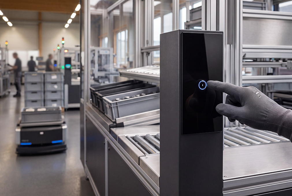
  • Device fronts and panels in automation
  • Keypads for machine operation without physical
  • Highly reliable operating solutions in harsh environments

Hygiene-sensitive areas

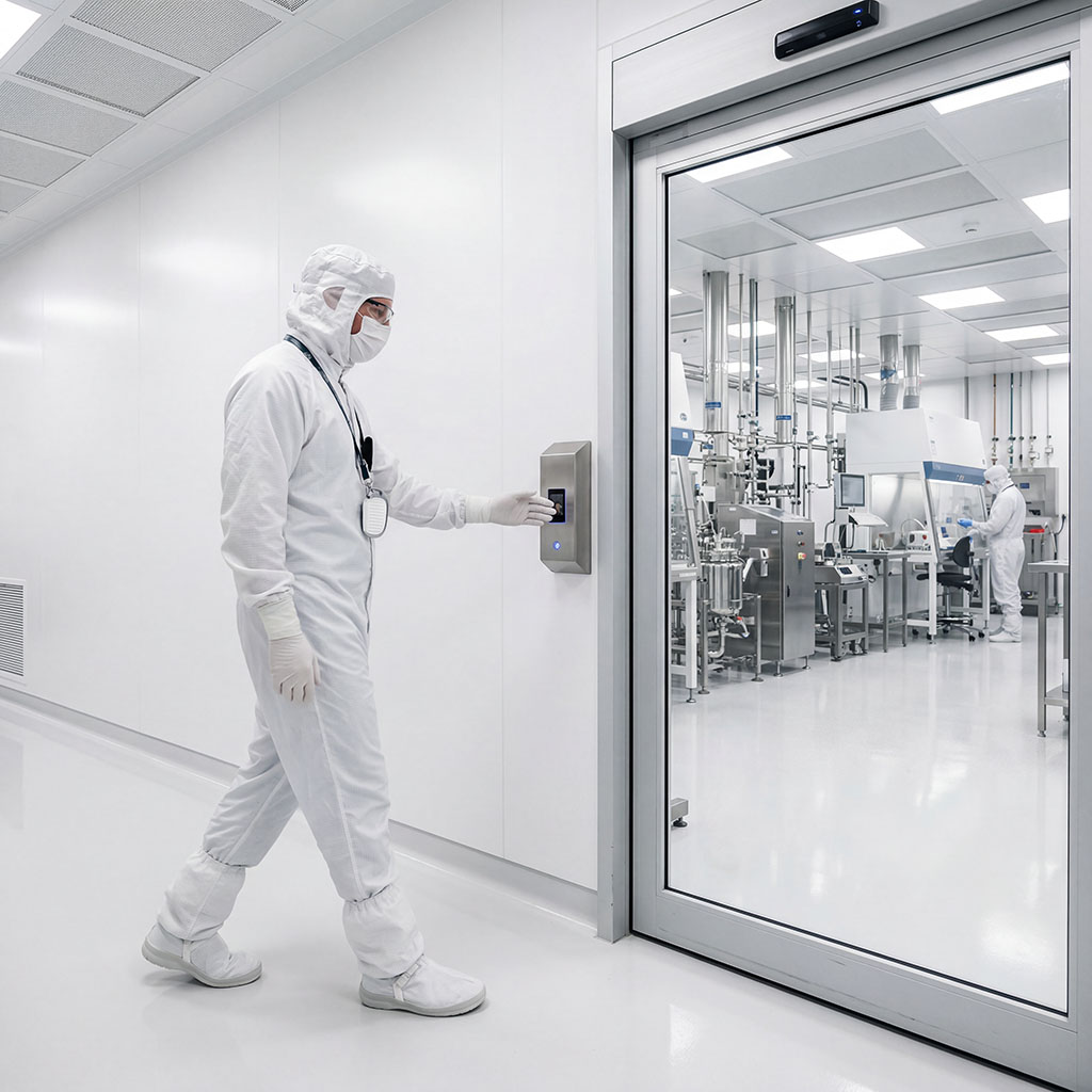
  • Input units for medical technology, laboratory equipment, or aircraft lavatories
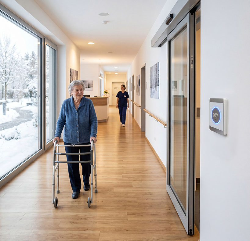
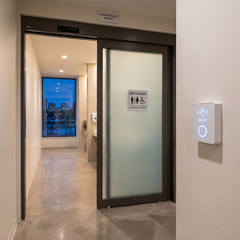
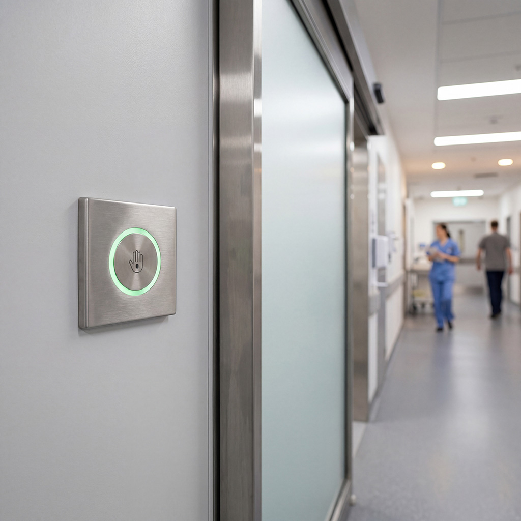
  • Controls for contactless door systems or device operation

Public institutions

  • Keyboards and input elements at information terminals
  • Access systems in hygiene-critical zones
  • Ticket machines and touchless kiosks

Use Cases

PTRA
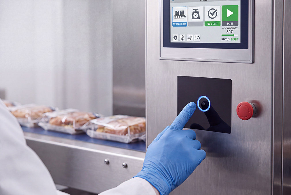
A practical example is the development of an optical keypad for a modern glass input panel – used in an industrial environment with special hygiene requirements.

Conceived by humans, visually realized with AI

Project brief

  • Client: PTRA
  • Product: Multimedia console
  • Areas of application: Mechanical and equipment engineering | Food industry & catering
  • Initial situation

    The goal was to find a touchless keypad solution that not only offers excellent functionality but also integrates seamlessly into a high-quality device design – with a focus on easy cleaning, visual feedback, and robust construction.
  • Solution

    Development of an optical keypad with

    • RGB-backlit controls,
    • responsive TOF analysis,
    • front glass cover (3mm),
    • configurable lighting logic.
  • Result

    The result is an easy-to-clean, hygienic control unit with a modern look and feel. It demonstrates how optical technology can be used where traditional buttons are no longer sufficient. Technical specifications (Example configuration):
    • External dimensions: ?? x ?? x ?? mm
    • Operating temperature: 0 °C to +70 °C
    • Storage temperature: -25 °C to +80 °C
    • Response time: 10 ms
    • Glass thickness: 3 mm
    • Illumination: RGB LEDs, integrated across the entire surface
    • Surface: closed, cleanable
    • Sensor technology: TOF-based (laser)
Robust Enter key in public areas
A practical example is the development of an optical sensor for applications in public areas with special hygiene requirements.

Conceived by humans, visually realized with AI

Project brief

  • Client: PTRA
  • Product: Robust Enter Key
  • Areas of application: Public sector
  • Initial situation

    The goal was to find a touchless keypad solution with high design standards, low wear, and better hygiene than traditional keys.

    The focus was on easy cleaning, visual feedback, and robust construction.

  • Solution

    Development of an optical switch with

    • RGB-backlit controls,
    • fast response
  • Result

    A keypad unit has been developed that offers significant advantages in public areas (touchless, easy to clean) and combines these with a modern design.

    It demonstrates how optical technology can be used where traditional keys are no longer sufficient.

💡Tips from our R&D department:

Since each application places specific demands on design, environmental conditions, and operating logic, an individual feasibility study during the planning phase is recommended. This is the only way to ensure that the optical operating technology functions optimally, even in complex scenarios.

Let's talk about your project!

The more contactless the application,
the more important the know-how behind it.

We look forward to exchanging ideas with you!

Jens Kieselbach
Jens Kieselbach

Head of Innovation and Technology / Senior FAE

This email address is being protected from spambots. You need JavaScript enabled to view it.
LinkedIn

30 years of specialist expertise | 0.21% return rate | 740+ ready-to-use products | 10,000+ satisfied customers worldwide

The background image was conceived by humans and visually implemented using AI.

Developing optical user interface solutions requires far more than just the right sensor; it demands a deep understanding of light guidance, materials, and the interplay between design and technology.

Our strength lies in translating your requirements into a precise, durable, and intuitive solution: from concept to series production.

FAQs for technical decision-makers

TOF or reflection: Which is better suited?

It depends on the application. TOF is typically more robust against changing surfaces (transit time rather than intensity). Reflection is often easier to integrate, but can be more surface-dependent.

What is the typical detection range?

Depending on the sensor/use case, up to 1 m; for push-button use cases often ≤ 30 cm (more possible).

How is the timing/user feel adjusted?

Firmware parameters such as Filter and Holdoff as well as trigger logic (Mapping distance/signal -> event).

Which standards must be met?

Project-specific details must be coordinated before development begins, especially regarding EMC. Optical technologies offer advantages here due to their relative insensitivity to interference and very good hygiene properties; high IP protection ratings are readily achievable with sealed surfaces.

How can false triggers and incorrect operation be reduced?

Typical measures include dynamic thresholds, plausibility checks (e.g., temporal/physical consistency of signal or distance profiles), and multi-sampling with filtering and holdoff. Additionally, constructive measures such as clean decoupling of transmitter/receiver and the reduction of partial reflections in the beam path are helpful.

What safety requirements apply to laser-based optical systems?

When using laser-based light, the system must meet the requirements of IEC 60825-1 (eye-safe). The classification depends on the specific design (optics, power, operating modes) and should be clarified early in the project.

What are the requirements for cover material?

Transparent cover ideally ≥ 80% transmission, 2–4 mm; coatings must not scatter/filter the beam path.

Indoor or Outdoor?

Preferably indoors. Outdoor use is possible, but significantly more demanding; direct sunlight and heavy soiling should be avoided or detected and addressed via firmware.

The background image was conceived by humans and visually implemented using AI.

Autor

Where experience meets expertise

Jens Kieselbach

Head of Innovation and Technology