Capacitive input technologies for professional control units
What are capacitive input technologies and capacitive sensors?
A capacitive sensor enables robust, enclosed control units without moving parts – ideal when hygiene, protection level, design freedom, and low maintenance are paramount. Instead of mechanical contact, a change in electrical parameters (capacitance or impedance) caused by approach or touch is evaluated. This allows keypads, sliders, and wheels to be integrated behind glass or plastic, sealed on the front, and easily cleaned. For developers, the decisive factor is not the basic principle, but the overall design, including sensor layout, stack-up, electronics/firmware, EMC/ESD, and environmental influences, especially humidity and water.
A capacitive sensor detects touch via a measurable change in the capacitance of a sensor element. The sensor element is typically an electrode on a circuit board or a transparent electrode on glass (e.g., ITO).
The front can be designed to be closed, which simplifies protection level and hygiene.
This requires actively controlling sensitivity, interference immunity, and drift due to environmental influences, for example through calibration, filters, and EMC/ESD design.
Conceived by humans, visually realized with AI
Quickly find the relevant content.
The background image was conceived by humans and visually implemented with AI.
How do capacitive sensors work?
Self- vs. Mutual Capacitance
In practice, two basic principles dominate: self-capacitance and mutual capacitance. Both measure a change in capacitance, but differ in their electrical model, number of channels, and typical interference patterns.
Self Capacitance
In self-capacitance measurement, the capacitance of each individual electrode is measured against "ground" or the electrical environment. When a finger approaches, the effective capacitance increases because the finger acts as an additional capacitance surface. This method is often very sensitive and well-suited for individual buttons or simple sliders.
Typical challenges include significant interference from parasitic capacitances (housing, conductor tracks, cables), water and moisture films, and coupling to adjacent electrodes. Multi-touch functionality is limited or requires additional logic.
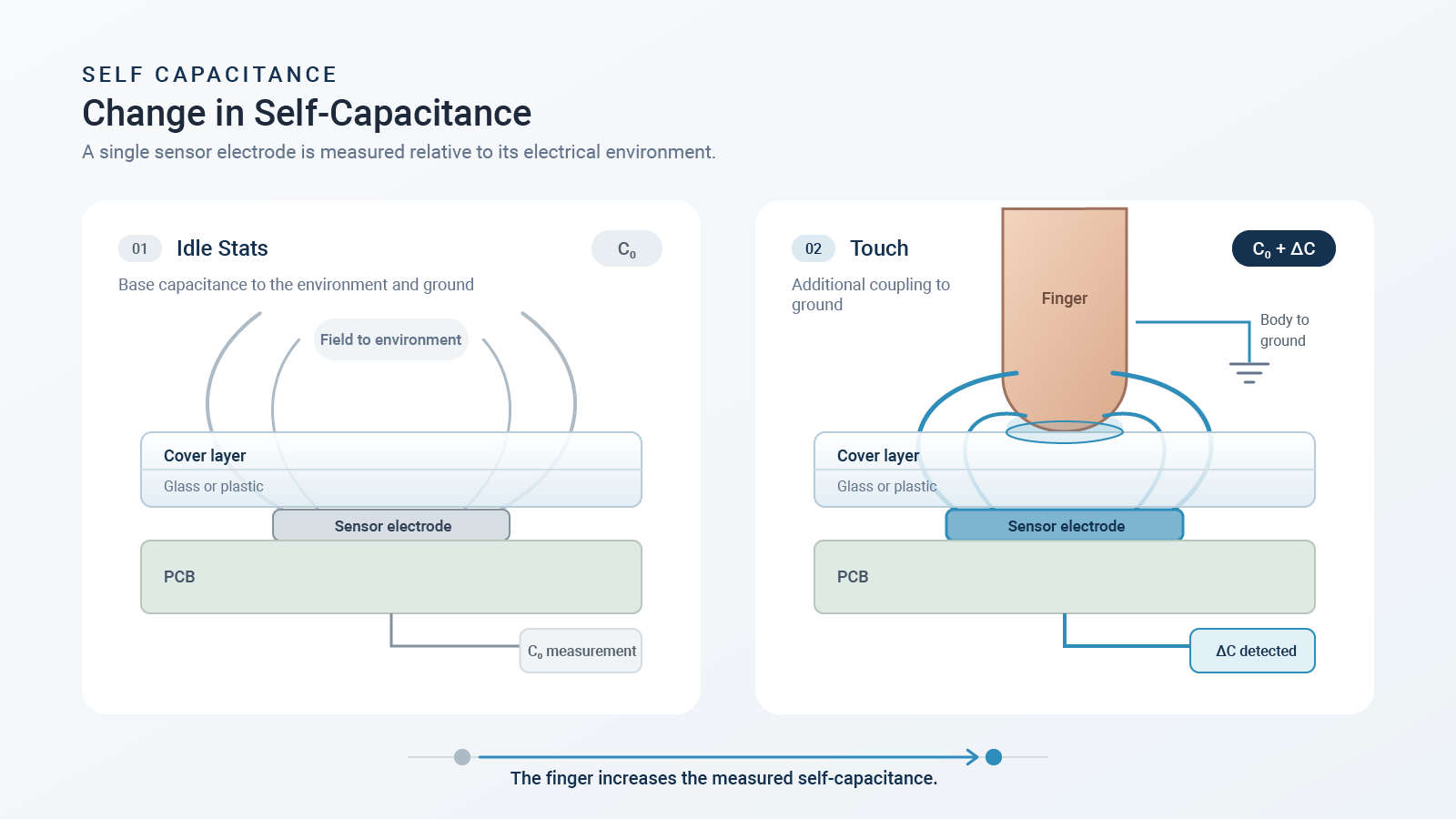
Conceived by humans, visually realized with AI
Mutual Capacitance
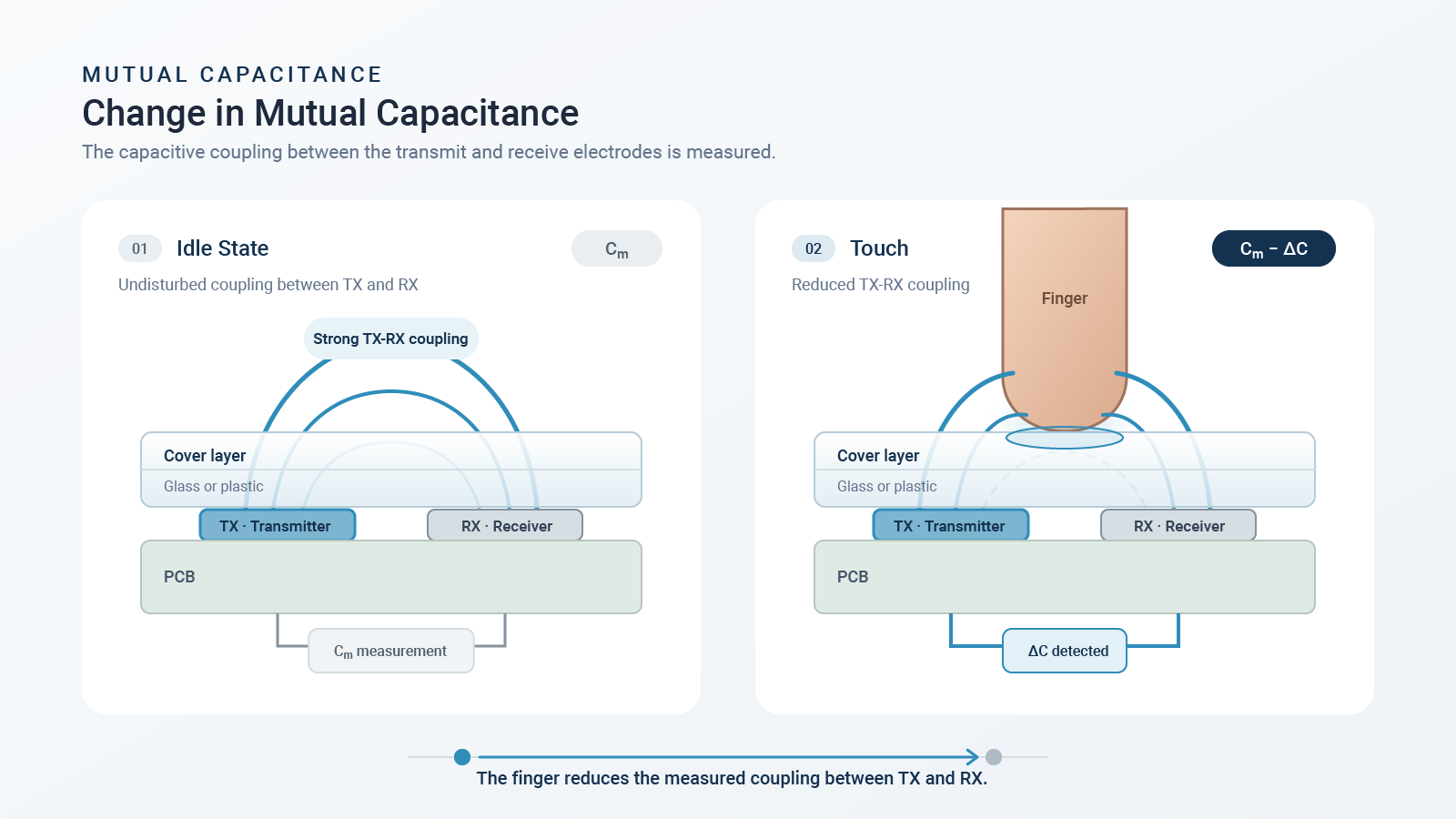
In mutual capacitance, the capacitance between a transmitting electrode (Tx) and a receiving electrode (Rx) is measured. In the quiescent state, a defined field component couples from Tx to Rx. A finger nearby alters the field (typically: shielding/diversion), thereby changing the measured coupling capacitance. Matrix structures and Multi-touch are therefore inherently easier to implement.
Directly applicable design rules of thumb
-
Design sensitivity based on sensor area, distance and cover material – do not “save it with software”.
-
Minimize and make air gaps reproducible; 1 mm of air can act like several millimeters of glass.
-
Testing moisture and water as a separate use case (water film, dew formation, cleaning conditions).
💡Tips from our R&D department:
-
Early testing with a real stack-up (material, thickness, adhesive, air gap)
-
Design the calibration to compensate for drift, but not to "calibrate away" any real touches.
-
Consider ESD and EMC already in the sensor layout (guard, grounding, filter, routing).
A robust input system is created through the interplay of sensor, cover material, and firmware.
For robust operation, the design is crucial: Avoiding (uncontrolled) air gaps is essential. Low-tolerance, long-term stable mounting close to the cover material is often helpful.
Conceived by humans, visually realized with AI
Where and when are capacitive sensors used?
A capacitive sensor particularly demonstrates its advantages when a closed front, easy cleaning, or high levels of protection are required. Its strengths lie in individual buttons, keypads, and control surfaces that are not designed for rapid typing. These are classic applications for capacitive buttons and capacitive switches.
Conceived by humans, visually realized with AI
Industrial applications
Hygiene-sensitive areas
Smooth and disinfectable surface, frontal sealing and safe operation even in humid conditions. The design must take water film and cleaning conditions into account.
Public institutions
Vandalism protection or robustness, resistance to changing users, environmental influences (rain or condensation) and clear feedback, both acoustic, visual and haptic.
💡Tips from our R&D department:
-
First define the use case based on the environment and operator (gloves, wet conditions, EMC), then select the technology.
-
For public systems, explicitly specify feedback and user error (glove/wet).
-
For hygiene applications, include cleaning processes and chemicals in the tests.
Decision matrix | Which technology suits my use case?
Use-case criteria and recommendation
The following overview compares a capacitive sensor to typical alternatives based on the criteria that are most often decisive in series production projects.
Mechanical vs. Capacitive
Conceived by humans, visually realized with AI
Avoid typical mistakes
-
Sensors too small and sensitivity "turned up" -> drift and false triggers.
-
Uncontrolled air gaps or adhesive layers -> Serial deviations.
-
No wet or ESD/EMC tests in the final stack-up.
💡Tips from our R&D department:
-
Make decisions based on environmental factors and standards, not on what "feels good".
-
Incorrect operation is a systemic issue involving mechanics, sensors, firmware, and UI/feedback.
-
For long pipelines and large areas, consider additional capacity and filters early on.
Compact design guide for developers on capacitive sensors
A robust input system results from the interplay of sensor, cover material, and firmware. The design is crucial for reliable operation, especially the avoidance of uncontrolled air gaps. A low-tolerance, long-term stable mounting close to the cover material is often beneficial.
Cover material and thickness
Sensor layout and stack-up
Sensor size, shape, pitch, and conductor routing determine the basic impedance and signal deviation. Guard structures, clean grounding, and reproducible adhesive layers stabilize the series production. Transparent electrodes are possible with glass (e.g., ITO).
To avoid uncontrolled air gaps, glue or press the sensor onto the cover material. Check the assembly and tolerance chain; mechanical references and stops help maintain reproducibility of the setup.
EMC/ESD Quick Checklist
-
Define ESD paths (front → chassis/ground) and protect sensitive inputs.
-
Keep cables short, symmetrical and with a defined reference; use long sensor cables with a series resistor or filter if necessary.
-
Firmware: Debouncing, interference pulse detection, recalibration only in the "inactive" state.
💡Tips from our R&D department:
-
Stack-up freeze before series production starts - document adhesive, gap and tolerance.
-
Address ESD and EMC as part of the layout review, not just in the test lab.
-
Choose calibration intervals to correct for slow drift (temperature, humidity).
Electronics, firmware and interfaces in capacitive sensors
Interfaces
Touch controllers typically deliver debounced events, raw data, or position values and are connected to a host MCU via standard interfaces (e.g., I²C). Important parameters include scan rate, thresholds, filters, interrupt concept, and power-saving modes.
In principle, any interface is possible via the evaluation firmware; typical integrations include:
- PC- or embedded-related applications: USB or RS-232
- Stand-alone applications: Switching contacts or switching outputs (trigger event as a digital signal)
- The firmware allows for the implementation of capacitive pushbuttons (non-latching) and capacitive switches (latching).
Note: The specific interface should be derived from the target system (panel PC, MCU, HMI) and the standard requirements and defined early on.
Conceived by humans, visually realized with AI
Robustness through firmware
Performance
💡Tips from our R&D department:
-
Define the interface and event model early (event vs. raw data), as this determines the firmware effort.
-
Set up parameter tuning as a reproducible process (presets per stack-up).
-
For low-power applications: Adjust wake-on-touch and scan intervals to suit the use case.
-
Provide a diagnostic option for commissioning and service (raw values, quality flags, event logging) to accelerate parameterization and troubleshooting.
Use Cases
Typical application: Robust machine and plant operation with a closed front.
Focus: Clear feedback, EMC/ESD robustness, and defined mounting.
-
Initial situation
The goal was to find a touchless keypad solution that not only offers excellent functionality but also integrates seamlessly into a high-quality device design. The focus was on easy cleaning, visual feedback, and robust construction. -
Solution
Development of a capacitive keypad with
- RGB-backlit controls,
- Self-capacitance technology,
- Fast response,
- Front glass cover and
- Light logic that can be configured even during operation.
-
Result
The result is an easy-to-clean, configurable control unit with a modern look and feel. It demonstrates how capacitive technology can be used where classic buttons are no longer sufficient and modern input elements are required.
Technical specifications:
- External dimensions: 255 x 40 x 9 mm
- Diffuser: 35 x 35 mm (optically usable) Power supply via USB: 5 V
- Power supply via plug: 9 bis 24 V; 250 mA @ 24V
- Operating temperature: 0 °C bis +70 °C
- Storage temperature: -25 °C bis +80 °C
- Response time: 10 ms
- Glass thickness: up to 6 mm
- 6 potential-free contacts: max. voltage 36 V DC; max. current 50 mA
- Illumination: Surface-mounted RGB LEDs, standard LED color: white (configurable)
- LED brightness: In standby – dimmed (orientation lighting), when activated – 100% brightness
Typical applications: Medical, laboratory and cleanroom.
Focus: Smooth glass front, easy disinfection, frontal sealing and stable operation under humid conditions.
-
Initial situation
The client sought a capacitive, flush-mounted keypad solution with a glass front that offered compelling functionality, a focus on easy cleaning, visual feedback, and a robust design. Key requirements included a locking mechanism for cleaning, user safety, and hygiene. -
Solution
Development of a capacitive keyboard with
- Mutual Capacitance Technology
- Flat Design
- 3 mm Glass Cover (Chemically Tempered Glass)
-
Result
The result is an easy-to-clean, configurable, flush-mount keypad with a modern design. It demonstrates how capacitive technology can be used where high hygiene standards and modern input solutions are required.
By using different cover glass, its format can be adjusted without any hardware changes.
Technical Specifications:
- 103-key keypad
- Fast response
- Front glass cover
- Adjustable: Sensitivity, acoustic feedback
- Cleaning button
- IP65 front protection
- Dimensions: 482 x 179 x 22.8 mm
- Material: Front: 3 mm, thermally tempered glass
Standard modules and customization
💡Tips from our R&D department:
-
For fast projects, first choose a reference design and then only adjust the stack-up and UI.
-
Plan audio or visual feedback as part of the user experience – it replaces missing haptic feedback.
-
Series production capability is achieved through controlled mechanics (gap, adhesive) and robust parameters.
Every project involving capacitive sensors has its own unique set of constraints: stack-up, environmental influences, user interfaces, and production goals are rarely identifiable from datasheets alone. In a brief, no-obligation consultation, we'll work together to determine which technology best suits your application, identify typical integration risks, and explore how your concept can be transformed into a production-ready solution with reasonable effort. This saves you iterations and allows us to gain an early understanding of your requirements.
Head of Innovation and Technology / Senior FAE
LinkedIn

- Use Case (dry/wet, gloved),
- Desired front material and thickness,
- Dimensions and design, interfaces,
- Target protection level,
- Standards and EMC environment,
- Quantities and
- Desired timeline.
We look forward to exchanging ideas with you!
The background image was conceived by humans and visually implemented using AI.
Developer cheat sheet
-
Define Use Case: dry/wet, glove, EMC environment, cleaning, operating speed.
-
Set stack-up: Material, thickness, adhesive, air gap, distance sensor to cover.
-
Roughly dimension the sensor layout and verify it with a real-world sample.
-
Firmware parameter plan:Thresholds, filters, calibration, error states.
-
Test plan: ESD/EMC, water film/condensation, temperature/humidity, serial tolerances.
💡Tips from our R&D department:
-
Use the cheat sheet as the "Definition of Done" - this reduces iterations.
-
Any change to the stack-up or mechanics requires re-tuning.
-
Always perform tests in the final mechanical setup.
FAQs for technical decision-makers
What is a capacitive touch sensor?
A capacitive switch is a touch-sensitive control element without moving parts. Activation is detected via a measurable change in capacitance or impedance at an electrode.
How does a capacitive switch work?
An evaluation unit continuously measures the electrical characteristics of the sensor element. When a finger approaches, the electric field changes, and thus the measured capacitance or impedance. If a threshold is exceeded, a button press is triggered.
Where are capacitive switches used?
Typical examples are control panels with a closed front: medical technology, laboratory and cleanroom, food and pharmaceutical, industrial HMI, vending machines and information terminals.
What are the advantages compared to mechanical buttons?
Advantages include low wear, a closed and easy-to-clean surface, high design freedom, and high levels of protection on the front. Disadvantages include a lack of tactile feedback and increased sensitivity to environmental conditions.
Are capacitive buttons waterproof?
The front panel can be sealed very well. However, water and moisture remain a critical factor in terms of functionality – a film of water can mimic touchscreens. This must be addressed and validated through design and firmware.
Can capacitive switches be actuated through glass or plastic?
Yes. The crucial factors are material, thickness, air gap, and sensor size. Due to its higher εr, glass often allows for greater thicknesses than many plastics – the exact limits depend on the overall design and must be verified in a prototype.
What is the difference between capacitive and resistive switches?
Resistive systems react to pressure (contact between two layers), capacitive systems to changes in field or capacitance. Capacitive systems offer better sealed surfaces and less wear, while resistive systems are often less sensitive to water films but are mechanically and optically limited.
Can capacitive switches be operated while wearing gloves?
Often yes – depending on glove type, material thickness, and sensitivity. Glove operation should be specified as a separate use case and tested with actual gloves.
How do I connect a capacitive touch switch?
Typically, a touch controller scans the sensors and reports the results to a host MCU via I²C, SPI, or interrupt. Alternatively, simple self-cap designs can also be implemented directly with MCU peripherals, provided performance and robustness are sufficient.
The background image was conceived by humans and visually implemented using AI.
Autor
Where experience meets expertise